Golden
Era Model Service
High
Quality Plan Sets for Radio Control Aircraft
The Tlush Mite
Published in
the May 1938 Air Trails
Designed by Francis Tlush
Original span 50 inches

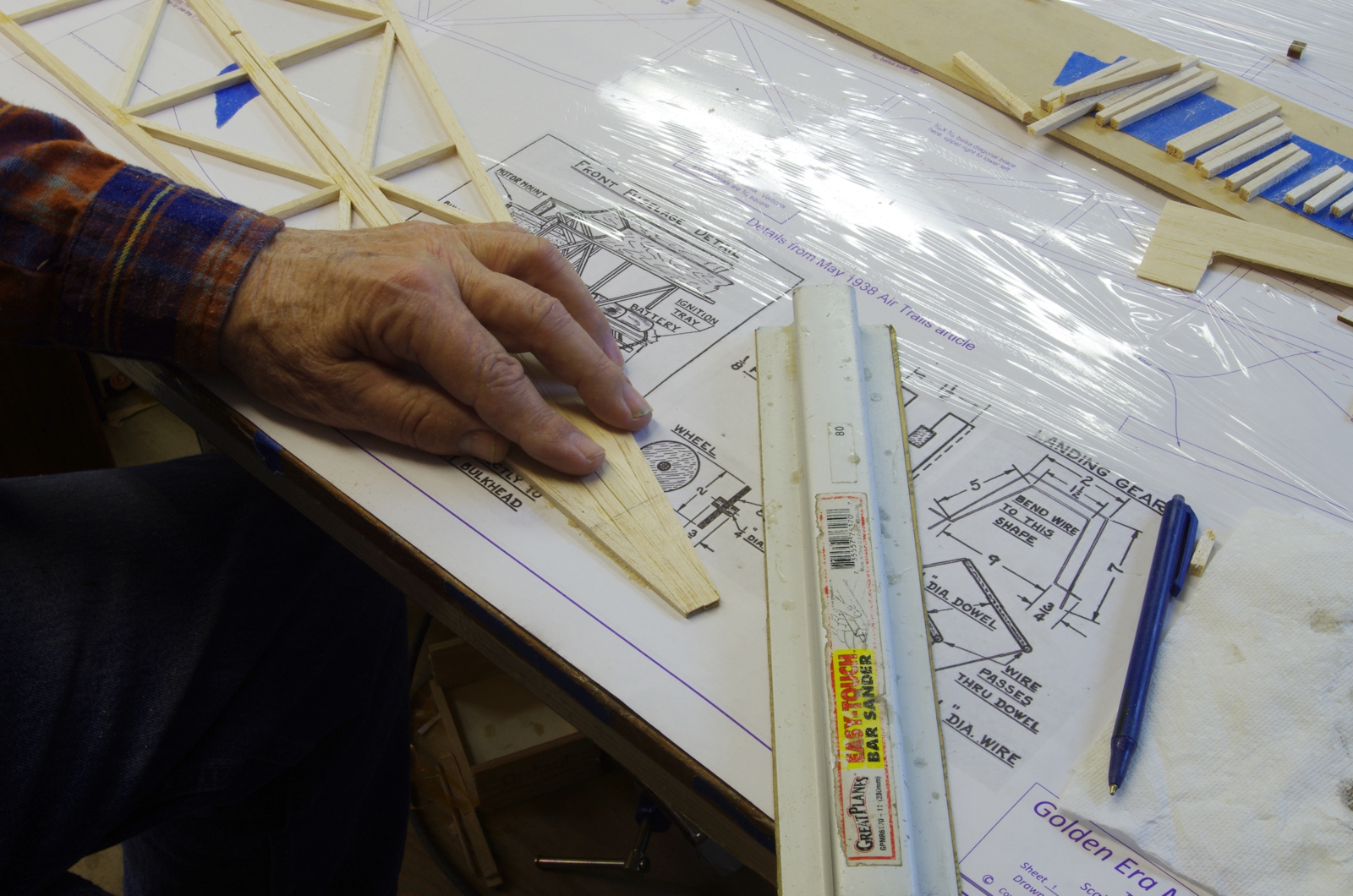
There
is a chart on the plans showing the overall lengths of the verticals,
diagonals, and crossmembers. It is easy and quick to cut them all
to size before
starting fuselage
construction. Sticking them in order on blue tape keeps things
organized. The end angles are sanded in as the fuselage is built, the
lengths on the chart allow for that. The digital caliper makes accurate cutting of the the parts easy. The cutting board is a length of 3/16 basswood sheet.

The
inset on the right shows a closeup of a useful tool for thin CA
application. It is a small diameter brass wire twisted up, with a
small fork formed in the end.
As
you can see capillary action draws a small amount of CA in to the fork.
When touched to a joint the CA flows in. A small amount of
fresh CA is kept in
the
depression in the bottom of the upturned medicine cup. The fork
will clog up, at which point the end of the wire is cut off and a new
fork formed.

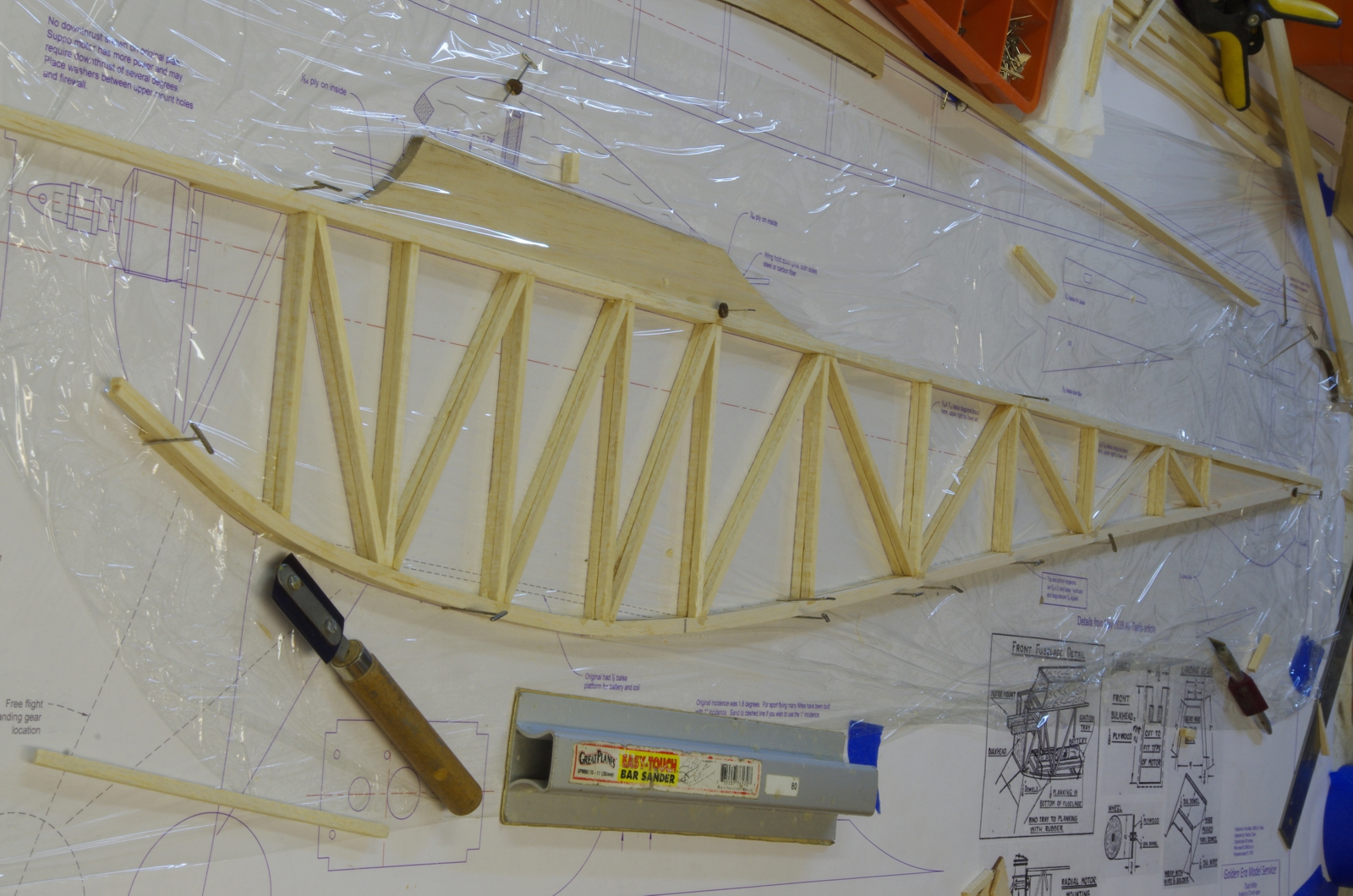
This
is the way the fuselage looked when built initially. The forward sections of the lower
longerons were sliced lengthwise to allow for making the curve
near
the
nose. Don't do like I did and install the wing saddle at this
point, it must be installed after the fuselage sides are joined
together with the frames flat
on the table upside down.

I
managed to run into a border board in a long landing, actually a rather
clumsy attempt to taxi closer to myself, and the lower fuselage proved
to be unequal to the task.
The
lower fuselage was modified during the repair to this configuration.
The laser cut part extends back one more cluster than my repair
part. The inside faces of the
keel parts are saw cut vertically to mid depth in the area of the rear
landing gear mount plate to allow for the inward bend there. The
landing gear plates
are
set in to the keels, locating them accurately and providing more
strength, also allowing the deletion of the balsa crossmembers in those
places.
The
second fuselage frame is built over the top of the first, with plastic
wrap between. Again, that wing saddle should not be there at this
point.
Tapering the inside faces of the aft ends of the fuselage frames.
Mite Page 1 Mite Page 2 Mite Page 3 Mite Page 4 Mite Page 5 Mite Page 6 Mite Page 7 Mite Page 8 Mite Page 9 Mite Page 10
GEMS
Index Page John Eaton's
Home Page